High Voltage AC Transmission Lines

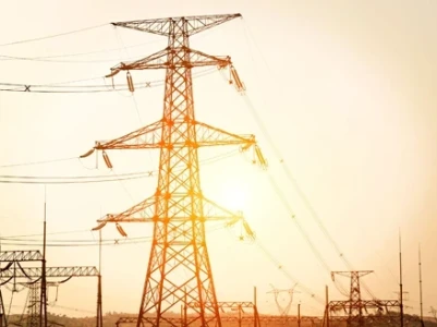
Three-phase electric power systems are used for high and extra-high voltage AC transmission lines (50kV and above). The pylons must therefore be designed to carry three (or multiples of three) conductors. The towers are usually steel lattices or trusses (wooden structures are used in Germany in exceptional cases) and the insulators are generally glass discs assembled in strings whose length is dependent on the line voltage and environmental conditions. One or two earth conductors (alternative term: ground conductors) for lightning protection are often added to the top of each pylon.
Detail of the insulators (the vertical string of discs) and conductor vibration dampers (the weights attached directly to the cables) on a 275,000 volt suspension pylon near Thornbury, South Gloucestershire, England. In some countries, pylons for high and extra-high voltage are usually designed to carry two or more electric circuits. For double circuit lines in Germany, the “Danube” towers or more rarely, the “fir tree” towers, are usually used. If a line is constructed using pylons designed to carry several circuits, it is not necessary to install all the circuits at the time of construction. Medium voltage circuits are often erected on the same pylons as 110 kV lines. Paralleling circuits of 380 kV, 220 kV and 110 kV-lines on the same pylons is common. Sometimes, especially with 110 kV-circuits, a parallel circuit carries traction lines for railway electrification.
High Voltage DC Transmission Pylons
High voltage direct current (HVDC) transmission lines are either monopolar or bipolar systems. With bipolar systems a conductor arrangement with one conductor on each side of the pylon is used. For single-pole HVDC transmission with ground return, pylons with only one conductor cable can be used. In many cases, however, the pylons are designed for later conversion to a two-pole system. In these cases, conductor cables are installed on both sides of the pylon for mechanical reasons. Until the second pole is needed, it is either grounded, or joined in parallel with the pole in use. In the latter case, the line from the converter station to the earthing (grounding) electrode is built as underground cable.
Raliway Traction Line Pylons
Pylons used for single-phase AC railway traction lines are similar in construction to pylons used for 110 kV-three phase lines. Steel tube or concrete poles are also often used for these lines. However, railway traction current systems are two-pole AC systems, so traction lines are designed for two conductors (or multiples of two, usually four, eight, or twelve). As a rule, the pylons of railway traction lines carry two electric circuits, so they have four conductors.
Read full article in the Electrical Reliability Systems Special Edition 2022

