Fiberglass Reinforced Polymer Crossarms 5th Percentile Design Strength Value Development
NFPA 70E Training
Our customized live online or in‑person group training can be delivered to your staff at your location.

- Live Online
- 6 hours Instructor-led
- Group Training Available
Introduction
In 2007, the National Electric Safety Code (NESC) standards committee adopted composite poles, crossarms, and braces into the code. This action was significant in mandating the composite electrical structures manufacturing industry to publish their design strength values to a 5% Lower Exclusion Limit (LEL). We published a white paper that creates transparency for the utility engineer, in that it describes the test methods, test setup, statistical calculations and relevant standards utilized to generate 5th percentile design strength values for Creative Pultrusions, Inc. (CPI) CP2500 series crossarm. The following is an abbreviated version of that white paper. You can find the complete writing on our website under Technical Papers.
Investigation
The following mechanical characteristics were evaluated to obtain the 5th percentile strength values for design, standards development, and quality control purposes:
Bending Strength at Failure for Deadend and Tangent Crossarm
In-plane Shear Strength at Failure
Flexural Modulus of Elasticity
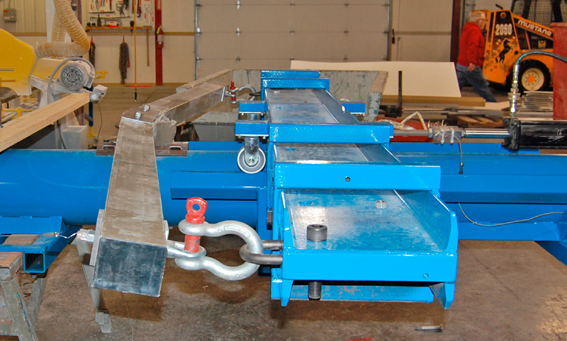
Experiment
Crossarm lengths, ranging from 5' to 12', were tested in both deadend and tangent configurations. The 3-5/8" x 4-5/8" deadend crossarms were assembled with grade 50 steel braceless deadend brackets, mounted to the crossarm with 3/4" diameter galvanized A325 grade bolts. The phase hardware consisted of 5/8" double arming (DA) bolts, 3.5" square x 3/8" thick washers, eye nuts, and lock washers. Deadend crossarms were tested in a three-point bend configuration. The arms were suspended by the 5/8" phase hardware simulating conductor loads, while the load was applied through the center mount bracket until a failure occurred. Both major and minor axis bending strengths were scrutinized. Tangent crossarms were tested in the tangent test fixture until failure. A steel pipe, representing a pole structure, supported the crossarm in a tangent configuration while the phase loading was applied into the crossarm through 5/8” DA bolts until failure occurred. For both the deadend and tangent tests, the load and deflection measurements were obtained using a calibrated load cell, displacement head, and/or a series of string pots. The data was logged into a database using a data acquisition center at a rate of two data points per second.
Sign Up for Electricity Forum’s Newsletter
Stay informed with our FREE Newsletter — get the latest news, breakthrough technologies, and expert insights, delivered straight to your inbox.