Grounding System Testing: Simplified Fall-Of-Potential And Step-And-Touch Voltage Testing

NFPA 70E Training
Our customized live online or in‑person group training can be delivered to your staff at your location.
- Live Online
- 6 hours Instructor-led
- Group Training Available
Verifying the functionality and integrity of a grounding system is critical to maintaining a safe workspace. Unfortunately, the tests used to achieve this goal, as well as the standards used to assess them, have required a specialized skillset, often leaving these tests done improperly or not at all. Now, with the industry progressing toward guided testing, new solutions make it possible for these tests to be performed correctly and accurately with limited test-specific training. Ultimately, this makes the difficulty of testing a ground grid similar to that of testing a transformer or circuit breaker. This article explains the purpose and theory behind grounding system testing, as well as an explanation of how the test is performed.
Theory
During a ground fault, fault current circulates between the fault location and the substation source that is driving it. In order to establish a low-ohmic return path for the fault current, grounding systems are designed to allow a conductive low-ohmic connection between the soil and the neutral of the system where the fault is located.
In principle, a grounding system consists of conductive elements including wires, rods, etc. These elements have direct contact to soil and therefore allow a current to flow between the soil and the neutral. Each conductive element placed in the soil increases the surface area of the grounding system in contact with the earth and reduces the grounding system’s impedance. With each successive element added to the ground grid within a given area, the incremental benefit is reduced; however, it remains true that the more conductive elements in the soil, the better the grounding system is.
Sign Up for Electricity Forum’s Newsletter
Stay informed with our FREE Newsletter — get the latest news, breakthrough technologies, and expert insights, delivered straight to your inbox.
Figure 1 illustrates the potential in the event of a ground fault at the tower of an overhead transmission line. The return current through soil causes a potential rise of the grounding system and the tower where the fault occurs when compared to reference ground (illustrated here as the flat green plain surrounding the ground grid and fault location). Following electromagnetic field theory, the result of such an event is two upward and downward cone-shaped potential rises, as depicted in Figure 1.

The resulting potential rise, VG, is represented as the voltage between the grounding system and remote earth (a theoretical ground reference at an infinitely remote location, normally considered to be at zero potential). For testing purposes, remote earth is represented by the flat part around the grounding system’s potential rise, referred to as the reference ground. This zone is considered to be outside the area that is influenced by the grounding system.
To measure the connection between the grounding system and earth, ground impedance, ZG, is introduced:
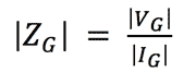
High ground impedance indicates a poor connection to reference earth. To reduce ground impedance, the grounding system must either be extended by additional conductive elements or repaired by replacing conductive elements that have deteriorated. This section explains how to determine the ground impedance.