Transient Analysis of Power Transformers Using Finite Element Method

NFPA 70E Training
Our customized live online or in‑person group training can be delivered to your staff at your location.

- Live Online
- 6 hours Instructor-led
- Group Training Available
A transformer relies on electromagnetic induction through coils to transfer electric energy between two or more circuits. Varying current in the transformer’s primary winding creates varying magnetic flux in the core, which produces varying electromotive force (EMF) or voltage in the secondary winding. Accurately and efficiently predicting currents and voltages on the primary and secondary windings can be challenging, especially for cores with non-linear material properties. Fortunately, numerical modelling techniques such as the Finite Element Method (FEM) enable analysis of key phenomena inside and exterior to a transformer, including currents and voltages in the windings, magnetic saturation of materials, heat generation by the coils and transformer core losses. This edited contribution to INMR by Chaowei Su, an R&D Specialist at INTEGRATED Engineering Software presents simulation results for three widely used types of transformers. Results were obtained using IES’s Oersted and Magneto 2-D programs as well as its Faraday and Amperes 3-D programs.
Applications & Discussion
Two-D and 3-D simulations were performed on three different types of transformers using a personal computer with Intel(R) Core™ i7-4930 CPU @ 3.40 GHz and 64 GB RAM.
1. Single-Phase Transformer
The first application involved a simple, one-phase 120V/12V transformer with M19 silicon steel, non-linear material core and operated at 60 Hz.
Sign Up for Electricity Forum’s Newsletter
Stay informed with our FREE Newsletter — get the latest news, breakthrough technologies, and expert insights, delivered straight to your inbox.
Fig. 2 shows the geometric models in 2-D and 3-D.
Fig. 3 plots the currents on input and output ports versus time for a transient input voltage source: V(t) =120sin(ωt)(V).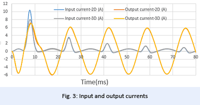
As seen in Fig. 3, inrush currents on the primary coil obtained by the 2-D and 3-D methods are similar, except for the first peak. Fig. 4 plots magnetic flux density of the inrush currents inside the core in both 2-D and 3-D at the second peak, t=0.025s.
Transformer inrush currents are high-magnitude currents generated when transformer cores are driven to saturation during energization. These currents have undesirable effects, including potential damage or loss-of-life to the transformer and reduced power quality for the system. Therefore, prediction of inrush current is an important issue in transformer design. Transient simulation offers an effective approach to analyze inrush currents.
Read full article in the Overhead & Underground T&D Technologies Special Edition 2022
INTEGRATED Engineering Software advertisement in the Overhead & Underground T&D Technologies Special Edition 2022: