Emergency Power for Data Centers

Why not all static UPS systems are created equal
BY KARLA E. BERT, P.E., Mitsubishi Electric Power Products, Inc.
In our cloud-based digital world, data must be available 24 hours a day, seven days a week—no matter the state of the electrical grid. Computer downtime not only affects production, but also negatively affects customer good will—quickly affecting an organization’s bottom line. In fact, according to the Meta Group, the cost of downtime can average a million dollars per hour for a typical data center. For this reason, Global Industry Analysts, a marketing research firm, predicts that the global uninterruptible power supply (UPS) market will reach $14 billion (USD) by 2017. However, it is important to know that not all static UPS systems are created equal.
Choosing a backup power solution that makes the best sense—in terms of reliability, efficiency, maintenance, and return on investment—are key considerations. Additionally, lowering a facility’s energy footprint through conservation is an important goal; however, not at the expense of reliability. Electrical Source Magazine will discuss how advances in three-phase static UPS systems offer increased reliability and efficiency through smarter engineering, mitigation of power losses, and improved power conversion processes that result in higher overall efficiencies.
WHAT IS A STATIC UPS?
Simply put, a static UPS system provides instantaneous backup power when the utility power fails. The secondary function of conditioning the power so that other anomalies (sags, surges, harmonics, switching transients, frequency variations) on the utility line do not damage equipment is included on some, but not all UPS systems.
Companies buy one of two main types of UPS systems—off-line or line interactive and on-line double conversion. Single-conversion UPS systems run on utility power until the UPS senses a problem and then reverts to the alternative power source (typically batteries). These systems have an inverter for operation on batteries and some even have a power interface that can regulate the voltage even when not on battery. The downside is that these systems are not protecting the critical equipment continuously, but rather switch to conditioning mode.
An on-line double conversion UPS system takes the utility power and deconstructs the alternating current (AC) waveform to a direct current (DC) waveform using the converter/rectifier. The UPS system then reconstructs the AC waveform using the inverter to provide the critical load with a conditioned, pure AC sine waveform free of any distortion, sags, surges, and other imperfections that can damage sensitive electronic equipment. On the DC side, operators can introduce batteries, flywheels, or supercapacitors to the system to provide power when the utility is unavailable or out of tolerance.
The on-line double conversion UPS system provides constant voltage and constant frequency to critical loads. On-line double conversion UPS systems (refer to Figure 1) are the most reliable topology since they protect the critical equipment they serve 24 hours a day, seven days a week. This type of UPS is the focus feature moving forward.
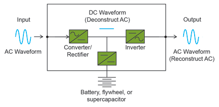
Figure 1: Static on-line double conversion UPS system
UPS CONVERTER TOPOLOGY
UPS converter topology has evolved over the years in order to increase efficiency, reliability, and generator compatibility. Early on, UPS rectifiers/converters used six-pulse diodes. As technology progressed, thyristor or silicon controlled rectifiers (SCRs), replaced diodes and manufacturers released 12-pulse rectifiers. These two newer types of rectifiers require large input filters to reduce the total harmonic distortion on the current waveform. Additionally, these filters create a leading power factor especially at low loads thus increasing the kilovolt-amperes (kVA) of the UPS system and posing problems for the generator. Some UPS system manufacturers still use this technology for their converters. As technology continued to advance, hybrid rectifiers started to appear on the market. These hybrid systems are a six-pulse diode bridge with an insulated gate bipolar transistor (IGBT) chopper circuit. These rectifiers reduce the input harmonics, but still require a sizable input filter for the current harmonics produced.
Additionally, these input filters create a leading power factor that feeds back to the generator under low load conditions. To compensate, technicians remove the capacitive element of the filters from the circuit usually at low loads where the leading power factor is the greatest. Instead of a significant leading power factor, the UPS system has severe current harmonics. For this reason, as well as the requirement of the 12-pulse rectifiers, many UPS systems have an input isolation transformer.
Insulated gate bipolar transistors emerged due to the advantages of using IGBTs that include the reduction of large input harmonic filters. The use of smaller filters reduces input current harmonics significantly and moves the unity power factor a step toward realization, which, consequently, eliminates original generator compatibility issues. Additionally, oversized generators are no longer necessary to compensate for leading power factor.
Since the UPS system does not require a larger harmonic input filter, operators can use a smaller radio frequency interference (RFI) filter to reduce overall costs. An additional added benefit is the increase in the overall efficiency of the UPS system. The use of the IGBT also supports dynamic front-end active control.
Initially, operators used insulated gate bipolar transistors in a two-level topology. Some manufacturers are now using a three-level IGBT topology to gain better efficiencies. This feature will discuss IGBT topology in the next section.
UPS INVERTER TOPOLOGY
UPS inverter topology started out as commutated thyristor to create the AC output waveform. This type of thyristor is easy to turn on, but must be turned off using forced commutation. Therefore, operators use snubber circuits to force the thyristor off. The snubber circuit is expensive adding to the cost of the UPS system.
Eventually, the inverter evolved into insulated gate bipolar transistors due to the ease of turning them on and off which allows for a quick control response. This quick control allows the UPS system to have a higher performance and improved reliability to produce an accurate output AC waveform.
The effects the IGBT has on the converter are also applicable on the inverter. The use of IGBTs reduces the output voltage harmonic distortion. Therefore, large output filters or output isolation transformers are not required. Minimizing harmonic filter magnetics and removing the isolation transformer from the equation increases overall IGBT efficiency.
THREE-LEVEL TOPOLOGY
There are many reasons to use a three-level topology over the standard two-level. When using a three-level topology, technicians must switch even more insulated gate bipolar transistors, but to only half of the DC voltage. This reduction lowers voltage stress and switching losses on the IGBT increasing UPS system reliability. The increase in conduction losses due the increase in the number of IGBTs combined with the lower switching losses creates a net overall efficiency gain over the two-level topology.
The output variable width pulse train of the three-level IGBT topology follows the sinusoidal waveform closer than the two-level (refer to Figure 2). This improvement in the creation of the AC waveform means significant noise reduction (both acoustic noise and electromagnetic interference); according to “The Power of Green” white paper, released by Mitsubishi Electric. These benefits improve the product specifications.
Using IGBTs for both the converter and inverter sections as well as the DC chopper of the UPS system makes other benefits possible for the UPS system, such as the transformerless UPS system, virtual neutral and better active front-end control.
There is a hidden benefit of using IGBTs in the DC chopper circuit. The higher switching frequency of the IGBT means that the DC ripple is also a very high frequency. If companies use batteries on the DC bus, the effect is that the ripple is too high of a frequency for the battery chemistry to respond, thus extending the life of the batteries.

Figure 2: Sinusoidal waveform
TRANSFORMERLESS TECHNOLOGY
Since companies use insulated gate bipolar transistors for the converter and inverter sections of the UPS system, transformerless UPS systems started to appear. UPS systems require advanced, reliable fault detection and protection circuitry in order to remove the transformer. Removing the transformer removes the efficiency losses of the transformer, thus creating a higher efficiency UPS system. A transformerless system does not have to consider the phase shift a transformer can put on the system. Additionally, a transformerless system removes the single point-of-failure as well as reduces weight and footprint. Since there is no transformer, there is no need for transformer impedance surge suppression.
 VIRTUAL NEUTRAL
The virtual neutral in a UPS system gives a neutral-to-ground reference point by connecting the common point on the input to the common point on the output. The virtual neutral connects to ground through a capacitor, which gives the system an equivalent ground reference voltage without a physical neutral-ground bond. This reference provides for line-to-neutral high frequency components from the input for cancellation with the same but opposite components on the output.
The best part of the virtual neutral is its reliability for sensing faults. A DC ground fault will produce a potential difference between the virtual neutral and ground and the UPS system will alarm. A phase-to-ground fault at the load when the upstream transformer is grounded will produce high amounts of current in the inverter phases that the UPS system will detect through its control logic and alarm. A phase-to-ground fault when the upstream transformer does not have a neutral-to-ground bond or when the UPS system is operating on battery will produce a potential difference between the virtual neutral and ground. Again, the UPS system will alarm.
UPS CONTROLS
UPS systems that possess the aforementioned functions create benefits for companies with data centers; however, proper control is the key to maximizing reliability. Control of the insulated gate bipolar transistor power devices is critical to achieving optimum performance characteristics for reliability and efficiency as well as functionality. A control system used that has set the bar consists of the following components: digital signal process (DSP) for measuring the voltages throughout the system and an application specific integrated circuit (ASIC)/field programmable gate array (FPGA) to measure the currents throughout the system.
The UPS system uses a minor current loop with a major voltage loop to provide quick, accurate response to the varying conditions the UPS system needs to handle. The DSP supplies information into the FPGA; the FPGA evaluates the information from the DSP and from the minor loop measuring current supplies the gate signals to the IGBTs in the inverter, converter and chopper circuits. This sampling frequency can be as high as 57.6 kilohertz (kHz), which is 960 times in one cycle of output voltage. This way the UPS system can control the output with a high precision regardless of step loads and transients the UPS system encounters.
This type of control makes a multi-module system (MMS) cross current control loop easier to regulate. In the MMS application, the same quick, accurate responses occur.
GREEN-ORIENTED DESIGN
Since the isolation transformers have been eliminated, the large harmonic mitigating filters have been removed, and IGBTs are used with the advanced control system in a three-level topology; the UPS system now has a smaller footprint, is lighter, and has significantly increased efficiencies even at low loads. These benefits equate to space savings, freight savings, lower emissions of heat, less cooling demand, energy savings, lower noise, and interference, which collectively, create a green-oriented, environmentally friendly UPS system.
FAMOUS LAST WORDS
In summary, when selecting a UPS system, choose one with true on-line double conversion preferably with three-level converter and inverter topology as well as an insulated gate bipolar transistor DC chopper circuit with high switching frequency. Determine if a transformer is necessary for the designed system. Verify that the controls are optimal for the type of UPS topology. Search for longer standard warranties that create a greater peace of mind knowing that the manufacturer stands behind their equipment. Finally, choose a UPS system with the highest efficiencies that meet the aforementioned criteria.
Karla E. Bert is a projects engineer for the UPS Division of Mitsubishi Electric Power Products, Incorporated.